Mobile Base for Multi-Robot Manipulation
Written on June 11th, 2017 by Elton Cheng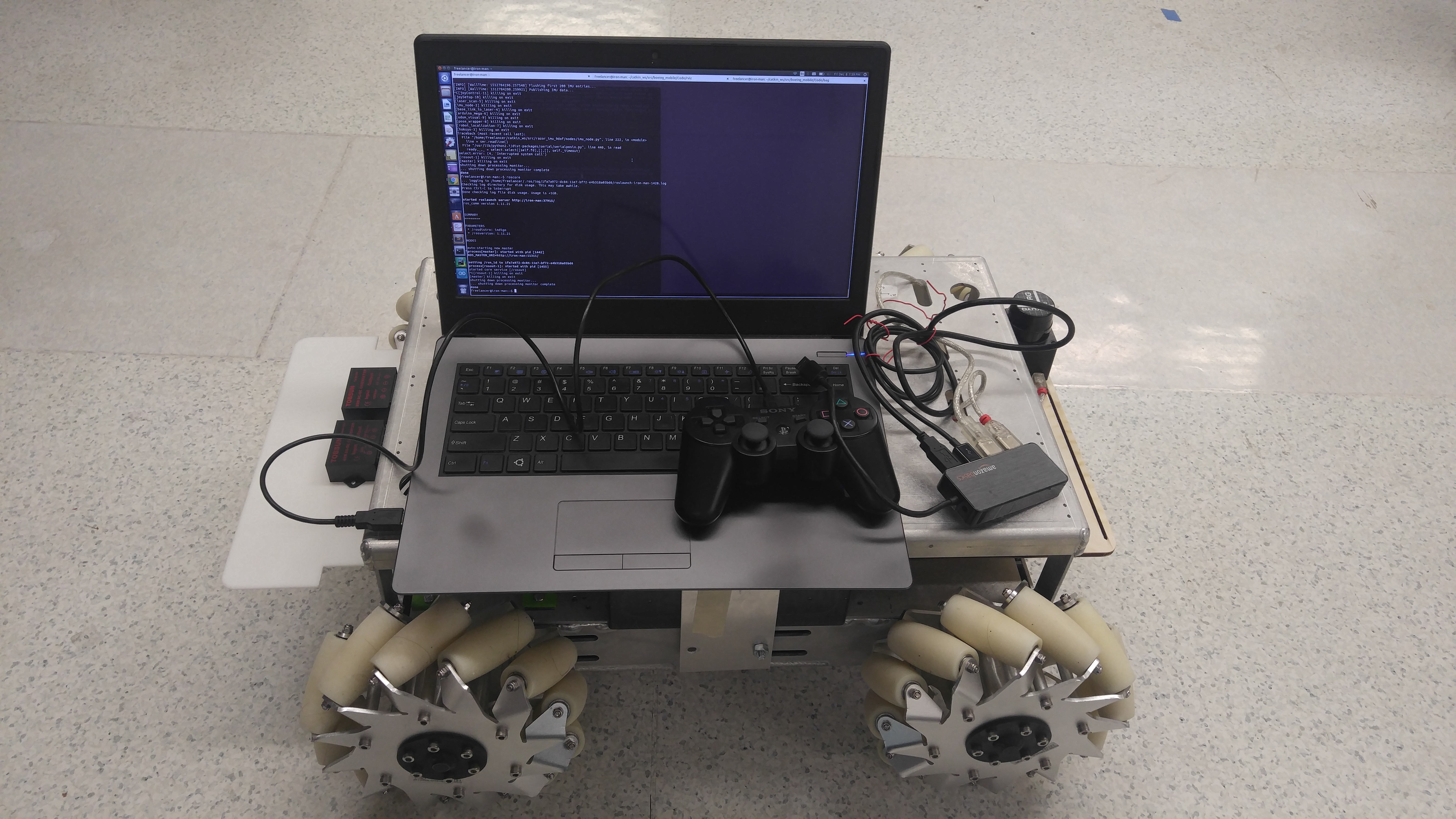
MSR Final Project: Mecanum Robot
Group Members: Chainatee Tanakulrungson, Yuchen Rao
Fall Quarter 2017: Final Assembly
Overview
The goal for Fall Quarter 2017 was to improve and make modifications to the design of the mobile base that would make it easier to maintain and build multiple copies. Documentation of the build process, components, and software can be found at the mobile base repository.


The secondary goal for this quarter was to also build up a localization library that would be setup for multiple combinations of sensors, such as Hokuyo URG-04Lx-UG01 laser scanner, Razor 9 DOF IMU SEN-14001, and motor encoder data of the wheels. Sensor data from these sources where then processed through their respective ROS software packages, and filtered through the ekf_localization_node of the robot_localization node to give a final filtered estimate of the position of the robot with respect to its starting position.
Below are two videos of the motion of the mobile base, and the odometry visualization of the mobile base in rviz. Complete documentation of this project can be found at the mobile base repository.
Spring Quarter 2017
Overview
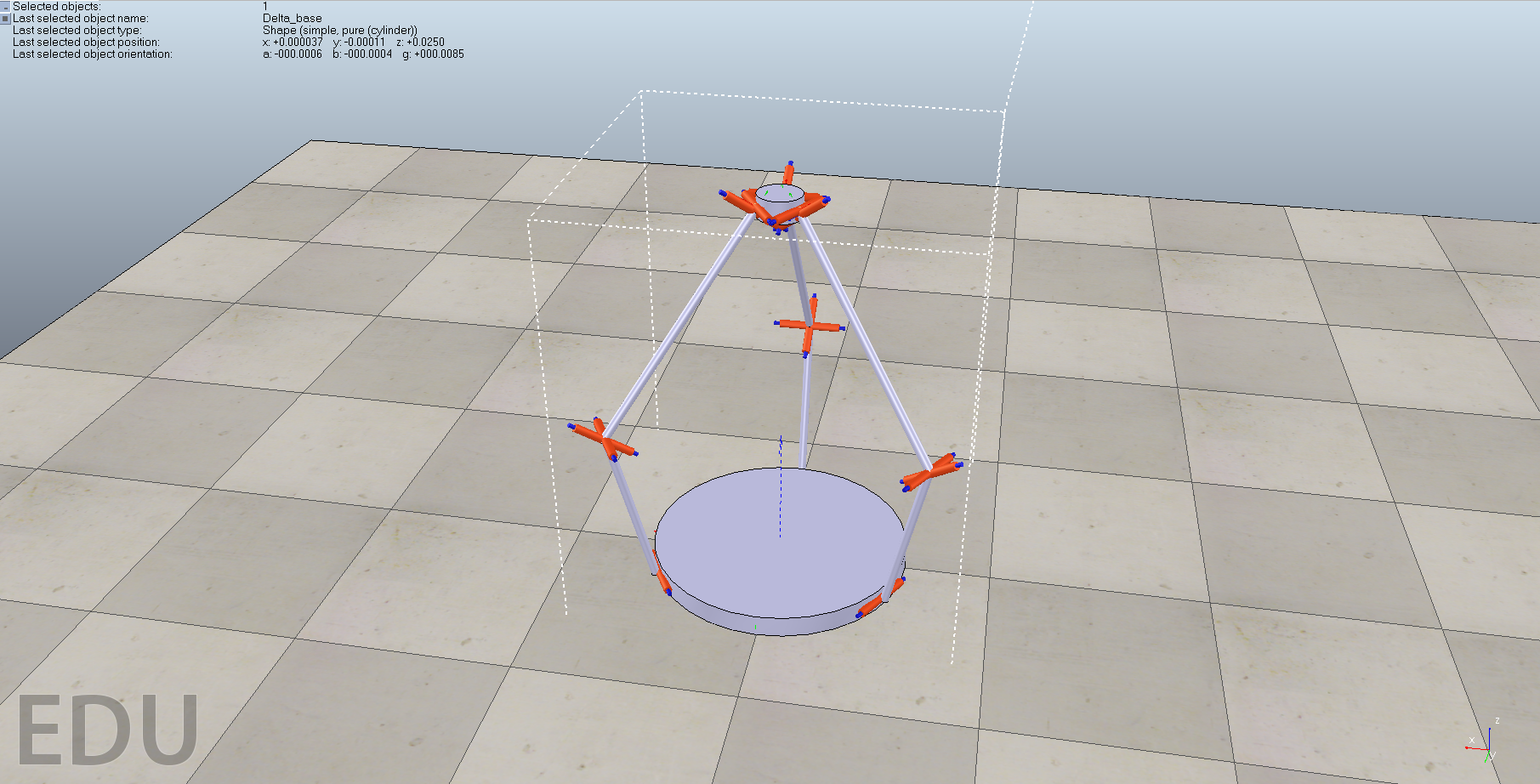
In collaboration with the NxR lab, ME398 Senior Design team, and MS in Mechanical Engineering students, the goal for this portion of the project was to source and control a mobile base for a system that allows 3 or more mobile manipulators to cooperatively position a large-scale manufacturing component.
The parts that make up this part of the project are: looking at our options for mobile bases, putting together the mechanical and electrical systems, and setting up the robot for R/C control.
Options for Mobile Bases
We needed to decide whether to purchase a pre-built base or a DIY kit which we can customize to our own needs. The specifications of our robot where we made our purchasing decision on were:
- Must be Omni/Mecanum wheeled. This is so that the orientation of the manipulators that will be eventually placed on the base will not rotate as the base is moving.
- Must be able to support at least 35 kg, due to the weight of the manipulator and the object it is carrying.
- Small enough that it can fit through a doorway, so it can be easy to move it around in our lab and for storage.
- Prefer 24V power supply that can be extended to other add-ons, as we expect the manipulators to be powered by 24V.
- Has a computer with ROS compatibility, as we want to be able to control the robot and manipulator with high-level software with a centralized computer.
- Ideally has encoders on each motor, to allow for velocity control and for calculating the robot’s position in the world
- Ideally less than $15,000.
Options that we were looking at include: the Neobotix MPO-500, Stanley Robotics Vector platform, Robotnix Summit XL, Superdroid Robots IG52 DB and Hangfa Robots Compass Q2 and Navigator Q2.
After going through these options, we decided to purchase the Superdroid Robots IG52 DB model as the kit we picked out met all the requirements except for #5. Due to the lower price tag of this kit (<$3000) and the ability to customize it to our needs, we believed that we can add our own ROS compatible Linux computer that will still keep the kit well below our budget.
Putting Together the System
Mechanical System
Putting together the mechanical system was straightforward, with the given suggestions provided in the kit manual.
The mechanical components for each wheel are composed of the motor, chain links, two sprockets, wheel axle, and a mecanum wheel. Each wheel was oriented in a certain way, such that the the expected moving behavior of the robot is known.


Electrical System
Design of the electrical system had to be different than the one provided in the manual, to allow for the future addition of the ROS computer and the delta robot manipulator.
In general, we had to layout how to provide 24V power to the motor setup, as well as create connections to 24V to 12V and 24V to 5V converters, which will be used to later power our ROS computer and microcontrollers. We also had to make the batteries easy to switch between charging mode and powering the robot. This was done by setting up XLR connections on the battery, robot, and charger.
The 24 V power feeds into the motor controller, which connects to two motors and a motion controller called the Kangaroo. The encoders of the motor are then connected to the Kangaroo to allow for automatic tuning of the control of the wheels.


Tuning the System and Setting up for RC Control
The Kangaroo has a feature that auto-tunes the control of the wheels. The tuning procedure is to put the Kangaroo in “Teach Tuning” mode and begin rotating both motors at the same time. After rotating the moters in the direction the motors will move in, pushing a button on the Kangaroo will begin the auto-tuning process.
The Kangaroo has been setup such that you can control each motor connected to it individually, and is in velocity control mode.
After the tuning process is complete, the control signals from the R/C receiver are connected to the control inputs to each Kangaroo. The controls are setup such that each axis of the joysticks control an individual wheel. For example, the throttle control (up-down on the left joystick) controls the back left wheel, while the rudder control (left-right on the left joystick) controls the front right wheel. The right joystick has a similar setup for the other wheels.

Putting Everything Together and Future Plans
Below is a video of the current state of our mecanum robot. It is currently setup to be controlled by a R/C transmitter.
Control of the robot using the controller is not as intuitive as with a typical R/C car, since you are now controlling independently each wheel. However, the use of the R/C transmitter is to check to see if the electrical and mechanical system is setup correctly, and that it moves the way we expect it to move.
Our future plans with the project over the summer and upcoming Fall quarter is to be able to control the robot with a microcontroller, complete the setup/communication of the Linux ROS computer to the microcontroller, and begin integrating the delta robot manipulator with the mobile base.
UPDATES
9/20/17: The PS3 controller can now be used to control the robot. On the Linux computer side, a ROS subscriber is used to listen the PS3 controllers and publishes the corresponding twist values. The arduino microcontroller code is set up to communicate with the Linux computer using ROS (rosserial_arduino and rosserial_python) and subscribes to the twist messages being published out. Encoder counts of the motors are polled by the arduino at a frequency of 75 Hz, which is then used to integrate and update the position of the odometry. This odometry is then published out back to the Linux computer to be used for analysis. Below is a video of the robot moving around in this configuration.
The next goal for this project is to experiment and analyze how accurate the odometry being published out from the robot is, and whether we need to improve it or not. This will be done by setting up several test scripts of different trajectories, such as a circle, square or line trajectory, that publishes out the necessary twists to complete this trajectory. By measuring the offset of the robot as goes through the trajectory with the published odometry, we can determine how accurate our odometry is.